ALFA PROCOMMUNICATION INFRASTRUCTURE Request a Quote

Fiber Optic Cable Termination Fabrication for Communication Sections

Fiber optic cable termination involves either splicing or connectorization to ensure low-loss, reliable connections in communication networks.Overview of Fiber Termination

Fiber optic termination is the process of preparing the end of a fiber optic cable to connect to another fiber, device, or network equipment. Proper termination is critical to minimize signal loss, prevent reflectance, and protect the fiber from physical damage or contamination ( ). Termination enables cross-connections and efficient distribution of optical signals in communication systems. There are two primary termination methods:

  1. Splicing – permanently joining two fibers end-to-end.
  2. Connectors – attaching removable connectors for flexible connections.
Splicing TechniquesFusion Splicing
  • Process: Uses an electric arc to fuse two fibers together.
  • Advantages: Lowest signal loss (typically 0.1 dB), high durability, ideal for long-distance or high-bandwidth applications.
  • Applications: Singlemode fibers, outside plant cables, and permanent installations.
  • Considerations: Requires specialized equipment (fusion splicer), clean environment, and precise alignment ( ).
Mechanical Splicing
  • Process: Fibers are aligned in a mechanical fixture with adhesive or gel.
  • Advantages: Easier to perform, suitable for temporary repairs or multimode fibers.
  • Disadvantages: Slightly higher insertion loss than fusion splicing.
  • Applications: Field restoration, multimode fiber splicing ( ).
Connector Termination

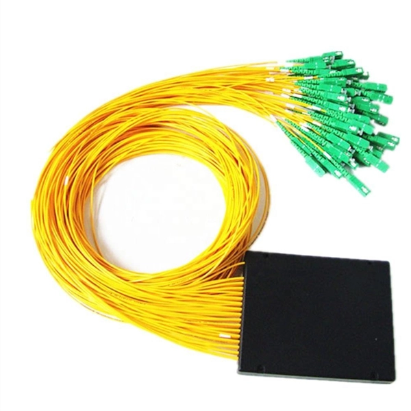
Connectors provide a removable interface for fiber optic cables, allowing quick reconfiguration in data centers or network panels. Common connector types include:

  • LC (Lucent Connector): Compact, high-density environments.
  • SC (Subscriber Connector): Push-pull design, easy insertion/removal.
  • ST (Straight Tip): Bayonet-style, legacy networks.
  • MTP/MPO (Multi-Fiber Push-On): Supports multiple fibers in one connector, ideal for high-bandwidth applications ( ).
Connectorization Process
  1. Cable Preparation: Strip the fiber jacket and clean the bare fiber.
  2. Cleaving: Cut the fiber end precisely to ensure a flat, smooth surface.
  3. Connector Assembly: Insert fiber into ferrule, apply adhesive if required, and cure.
  4. Polishing: For singlemode fibers, polish the ferrule to reduce reflectance.
  5. Testing: Measure insertion loss and return loss to ensure performance meets standards ( ).
Key Performance Metrics
  • Insertion Loss: Signal power loss at the connection point; lower values indicate better performance.
  • Reflectance: Light reflected back toward the source; minimal reflectance is critical for singlemode fibers.
  • Mechanical Strength: Ensures the termination withstands handling and environmental stress ( ).
Best Practices
  • Maintain a clean work environment to prevent dust contamination.
  • Use precision tools for stripping, cleaving, and polishing.
  • Follow manufacturer guidelines for connectors and splicing equipment.
  • Test all terminations with an optical power meter or OTDR to verify low-loss connections.
  • For singlemode fibers, consider factory-made pigtails for field splicing to ensure consistent performance ( ).
Summary

Effective fiber optic termination in communication sections requires careful selection between fusion splicing, mechanical splicing, or connectorization based on the application, fiber type, and network requirements. Adhering to proper fabrication procedures ensures low-loss, high-reliability connections that maintain network performance and longevity.

Fiber Optic Cable Termination Fabrication for Communication Sections

Optical fiber

An optical fiber, or optical fibre, is a flexible glass or plastic fiber that can transmit light from one end to the other. Such fibers are

Related Video Reference

This video was associated with the source search result. Verify technical details against current product documentation and project requirements.

Technical note

This reference is intended for preliminary fiber and communications infrastructure research. Optical interface, fiber type, port or core capacity, electrical input and output, enclosure protection, cooling, installation limits and applicable standards must be verified for the specific project.

Still Have a Technical Question?

Use the inquiry form to describe the product category, application, interfaces, capacity and installation environment.

Start a Project Inquiry