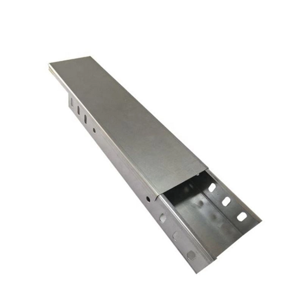
A high-voltage switchgear closing busbar is a conductive element that connects incoming power to circuit breakers and outgoing circuits, enabling safe and reliable power distribution within the switchgear.
Function and Role
In high-voltage switchgear, the busbar serves as the main conductor that carries electrical current from the incoming supply to multiple outgoing feeders or branches. It ensures smooth power flow, distributes current evenly, and allows circuit breakers to operate effectively for switching, protection, and fault isolation purposes. The closing busbar specifically refers to the section that connects the circuit breaker to the main bus, enabling the breaker to close and energize the circuit safely.
Busbar Types
Busbars in HV switchgear can be designed in several forms depending on current capacity, space, and operational requirements: Rigid busbars: Solid copper or aluminum bars, strong and stable, suitable for high current. Flexible busbars: Thin copper layers or braided conductors, used where movement or vibration occurs, often connecting breakers. Flat busbars: Easy to install and cool efficiently, commonly used in compact switchgear.
Tubular busbars: Hollow, lighter, and improve cooling in high-current systems. Laminated busbars: Thin conductors with insulation between layers, reducing inductance and improving thermal performance. ConfigurationsHigh-voltage switchgear can use single busbar, double busbar, or double circuit breaker arrangements.
Double busbar systems provide operational flexibility, allowing one bus to be isolated for maintenance while the other remains energized. A bypass bus can also be included to maintain supply continuity during breaker servicing. The closing busbar is integrated into these configurations to ensure that the breaker can safely connect or disconnect the load from the main bus.
Operational Considerations
Interlocking: Mechanical and electrical interlocks prevent accidental closing when maintenance is ongoing or grounding switches are engaged. Thermal and mechanical design: Proper sizing, spacing, and support prevent overheating and maintain stability during normal and short-circuit conditions. Maintenance: Draw-out breakers and sectionalized busbars allow parts of the switchgear to be serviced without interrupting supply.
Safety: Busbars are enclosed in metal or gas-insulated compartments to prevent accidental contact and ensure arc protection.
Summary
The closing busbar in high-voltage switchgear is a critical component that ensures reliable connection between circuit breakers and the main bus, supporting safe switching, fault isolation, and continuous power distribution. Its design, type, and configuration are chosen based on current rating, operational flexibility, and maintenance requirements, making it central to the performance and safety of HV switchgear systems.